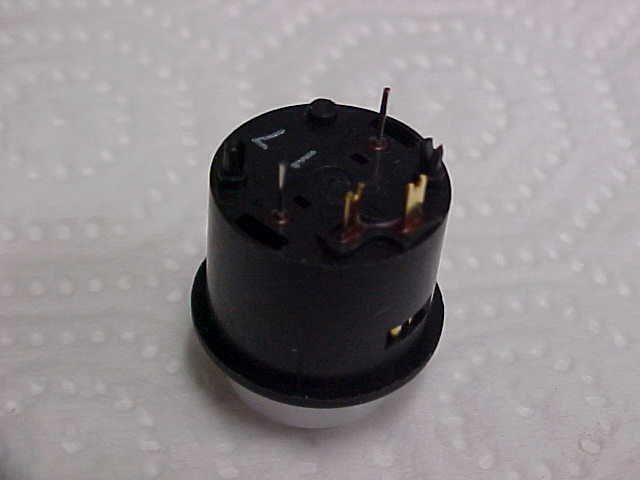
The 2 - thin, wire like terminals are the (incandescent - not LED) lamp. The 2 - brass/copper colored larger terminals are the momentary switch contacts. BTW, the (incond) lamp runs on 5 VDC and draws 61.1 ma. An equivalent LED draws approx. 2.28 ma. These pistons were sold by mcn-systems..
I have these same piston buttons and have converted them (a slightly time consuming task but well worth it) to use 3 mm LED's so as to use MIDI-Hardware's LITSW boards directly,
http://www.midi-hardware.com/index.php?R2=USD§ion=prod_info&product=LITSW Works great and with this (conversion to LED's) I don't need the LITBO power booster accessory. The LITSW boards can drive up to 3 ma each per LED.
I also made my own piston slips. The hole diameter for these pistons is 11/16" and I would suggest using a Forstner bit to drill the holes using a drill press. I found oak lattice boards available at Menard's work great. They come in 1/4" thick X 1 3/8" width well as 1/4" thick by 1 3/4" width. These 8 ft long boards are unfinished and take which ever stain you want to use very well. After the stain dried (in my case left the boards dry for 3 days) then sprayed them with medium gloss lacquer. And, of course let them dry another 3 days. Found if you stain both sides (at the same time) the boards tend not to warp at least not much.
If you use 3 mm high efficiency LED's they require a 1 K resistor in series to limit the current draw. I used 1/8 watt - tiny little guys that I actually was able to solder the resistor to the LED and together, they both fit inside the piston button housing. I solder them together before fitting them inside the piston housing. If anyone is interested in this "technique", you can PM me.
BTW, just to be (slightly) different, I used mostly white LED's for the c/a pistons, and then blue LED's for other functions. Flashing red LED's for the SET and the G/C
I also use ribbon cable to connect the (2 per) piston connections. In the case of the LITSW's, the same common (grnd) is used for the momentary push buttons as well as the common for the LED's. (in others words 2 separate wires for each piston plus the common bus rail), I ran a solid bus for this common and 2 separate connections (one for the switch and one for the LED) for each piston.
I soldered the 1 K resistor between the LED's short lead which is the cathode (-) and the common (grnd).
I also cut 3/4" X 3/4" by 1/2" thick wooden square dowel material to space the piston slips further forward to allow for plenty of rear clearance.
To keep the connecting (ribbon) cable in place, I carefully used round topped Arrow T 25 staples (shot) into the (back side) edge of the oak piston slip boards and ran the wire(s) thru them. Not enough space for conventional cable clamps.
Am considering using larger LED's near/above the toe pistons (controlling the Pedal c/a). Not sure how useful that would be considering most real pipe organ don't even have any lit thumb pistons. All this reminds me of my good neighbor who has so much chrome on his Harley, you can barely see the color of the bike.

Rgds,
Ed


